Torque Converter Clutch Pulse Width Modulation Solenoid, Torque Converter Clutch Solenoid, and Wiring Harness for Chevrolet Camaro 2000
Removal Procedure
Tools Required
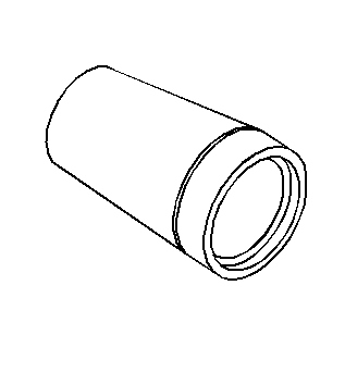
J 28458
Power Piston Seal Protector and Diaphragm Retainer Installer
- Remove the catalytic converter. Refer to
Catalytic Converter Replacement
or
Oxidation Catalytic Converter Replacement
in Engine Exhaust.
- Remove the transmission oil pan and the filter. Refer to
Automatic Transmission Fluid and Filter Replacement
.
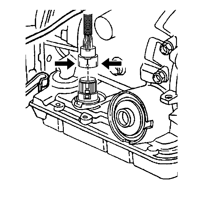
- Disconnect the transmission harness 20-way connector from the transmission internal harness pass-through connector.
Depress both tabs on the connector and pull straight up; do not pry the connector.
- Remove the 1-2 accumulator. Refer to
Accumulator Assembly, Spacer Plate, and Gaskets
.
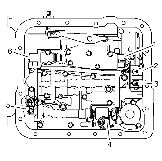
- Disconnect the internal wiring harness electrical connectors from the following components:
| • | Transmission fluid pressure switch (1) |
| • | 1-2 shift control solenoid (2) |
| • | 2-3 shift control solenoid (3) |
| • | Pressure control solenoid (4) |
| • | 3-2 control solenoid (6) |
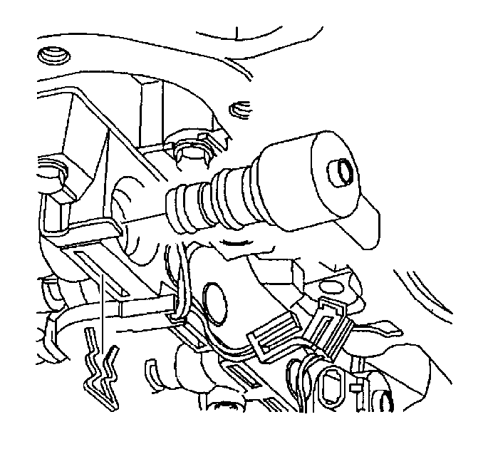
- Remove the TCC PWM solenoid retainer.
- Remove the TCC PWM solenoid in order to access one of the TCC solenoid retaining bolts.
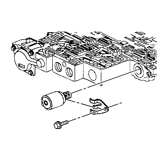
- Remove the pressure control solenoid retainer.
- Remove the pressure control solenoid.
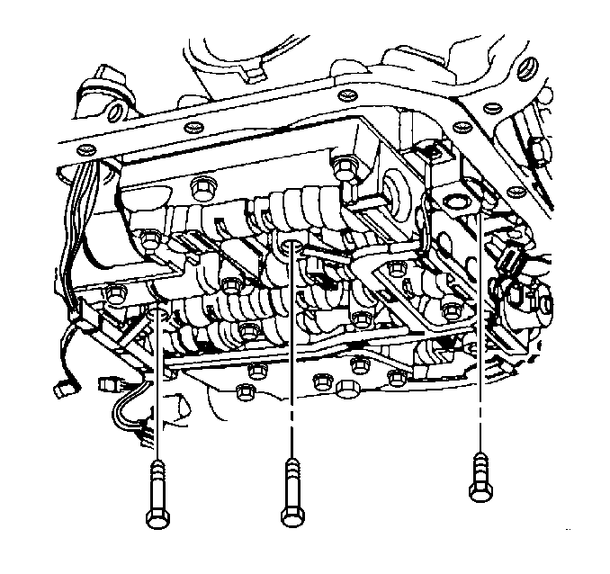
- Remove the TCC solenoid retaining bolts and the valve body bolts which retain the internal wiring harness.
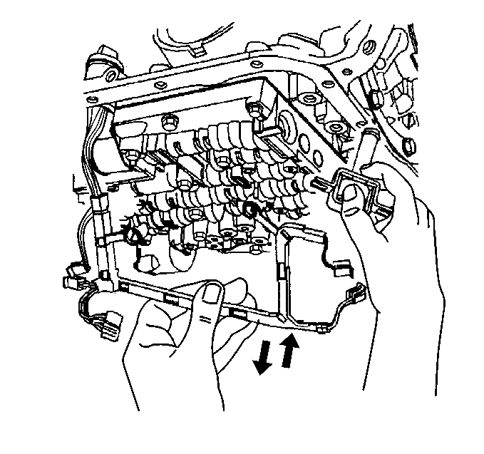
- Using
J 28458
, release the pass-through electrical connector
from the transmission case.
| 11.1. | Use the small end of the
J 28458
over the top of the connector. |
| 11.2. | Twist in order to release the four tabs retaining the connector. |
| 11.3. | Pull the harness connector down through the transmission case. |
- Remove the TCC solenoid (with O-ring seal) and wiring harness assembly from the transmission case.
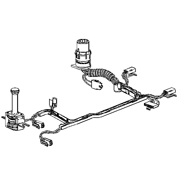
- Inspect the TCC solenoid and wiring harness assembly for the following defects:
Installation Procedure
- Install the wiring harness and TCC solenoid assembly with a new O-ring seal to the valve body.
- Install the pass-through electrical connector to the transmission case.
Notice: Refer to Fastener Notice in the Preface section.
- Install the valve body bolts which retain the internal wiring harness and install the TCC solenoid retaining bolts.
Tighten
| • | Tighten the control valve body retaining bolts to 11 N·m (97 lb in). |
| • | Tighten the TCC solenoid retaining bolts to 11 N·m (97 lb in). |
- Install the pressure control solenoid.
Ensure that the electrical tabs are facing outboard.
- Install the pressure control solenoid retainer and retaining bolt.
Tighten
Tighten the pressure control solenoid retaining bolt to 11 N·m (97 lb in).
- Install the TCC PWM solenoid to the control valve body.
- Install the TCC PWM solenoid retainer.
- Connect the internal wiring harness electrical connectors to the following components:
| • | Transmission fluid pressure switch (1) |
| • | 1-2 shift control solenoid (2) |
| • | 2-3 shift control solenoid (3) |
| • | Pressure control solenoid (4) |
| • | 3-2 control solenoid (6) |
- Install the 1-2 accumulator. Refer to
Accumulator Assembly, Spacer Plate, and Gaskets
.
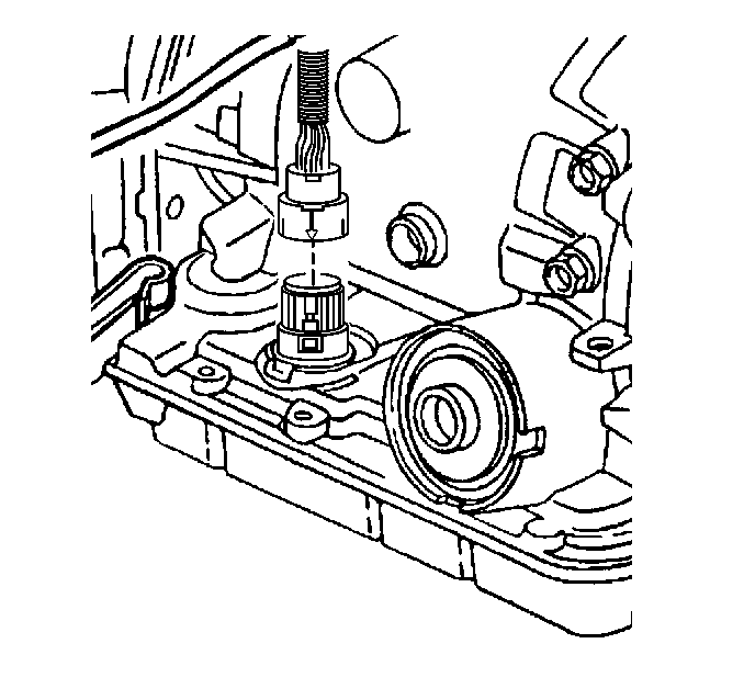
- Connect the transmission harness 20-way connector to the transmission pass-through connector.
Align the arrows on each
half of the connector and insert straight down.
- Install the transmission oil pan and filter. Refer to
Automatic Transmission Fluid and Filter Replacement
.
- Install the catalytic converter. Refer to
Catalytic Converter Replacement
or
Oxidation Catalytic Converter Replacement
in Engine Exhaust.
Important: It is recommended that the transmission adaptive pressure (TAP) information be reset.
Resetting the TAP values using a scan tool will erase all learned values in all cells. As a result, the ECM, PCM or TCM
will need to relearn the TAP values. Transmission performance may be affected as new TAP values are learned,
- Reset the TAP values. Refer to
Adapt Function
.