Steering Shaft, Lower Bearing, and Jacket - Disassemble - Off Vehicle for Chevrolet Corvette 2002
Steering Shaft, Lower Bearing, and Jacket - Disassemble - Off Vehicle Telescoping Column
Tools Required
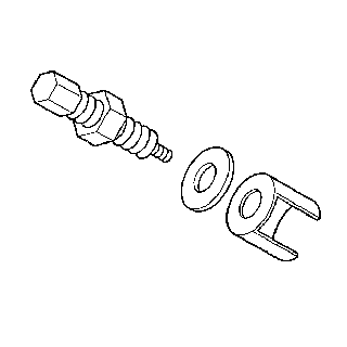
J 21854-01 Pivot Pin Remover
- Disable the inflatable restraint steering wheel module. Refer to Disabling the SIR System in SIR.
- Remove the signal switch housing. Refer to Turn Signal Switch Housing - Disassemble - Off Vehicle .
- Remove the tilt spring only. Refer to Tilt Spring - Disassemble - Off Vehicle .
- Remove the telescoping actuator assembly. Refer to Telescope Actuator Assembly - Disassemble - Off Vehicle .
- Remove the telescoping motor assembly. Refer to Telescope Motor Assembly - Disassemble - Off Vehicle .
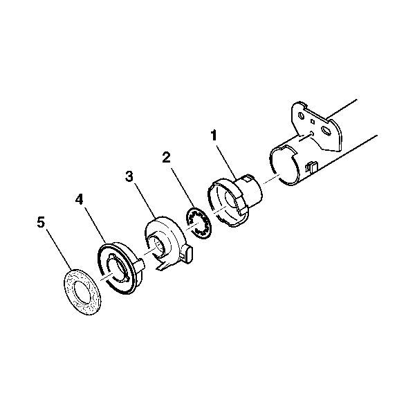
- Remove the steering shaft seal (5).
- Remove the sensor retainer (4).
- Remove the dual triangle sensor assembly (3).
- Remove the lower spring retainer (2).
- Remove the adapter and bearing assembly (1).
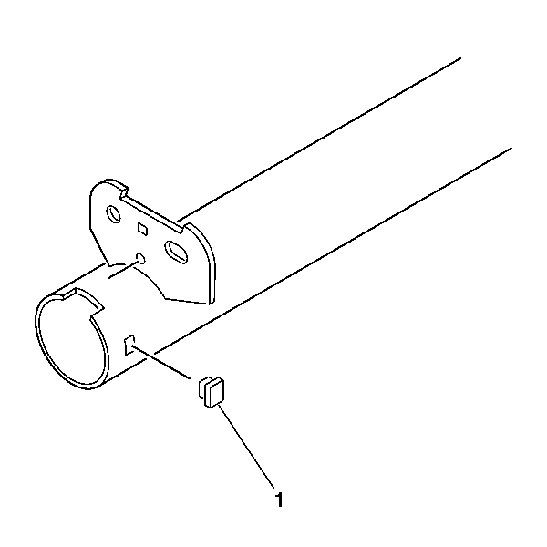
- Remove the switch housing blocking plug (1).
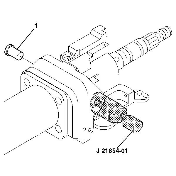
- Remove the 2 pivot pins (1) from the steering column support assembly using J 21854-01 .
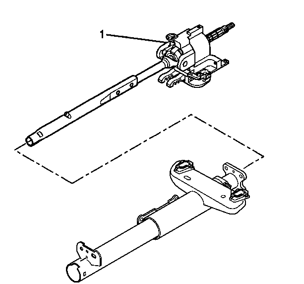
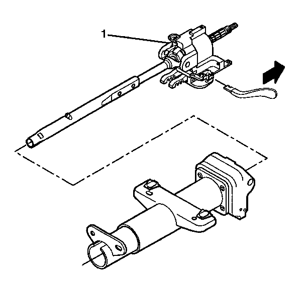
- Disengage the steering column lock shoes from the dowel pins in the steering column tilt head assembly (1).
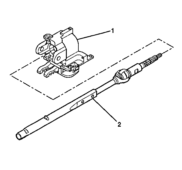
- Remove the steering column tilt head assembly (1) with the steering shaft assembly from the telebearing and jacket assembly.
- Remove the steering shaft assembly (2) from the steering column tilt head assembly (1).
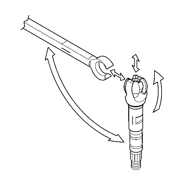
- Mark the race and upper shaft assembly.
- Mark the lower steering shaft assembly.
- Tilt the race and upper shaft assembly 90 degrees to the lower steering shaft assembly to disengage.
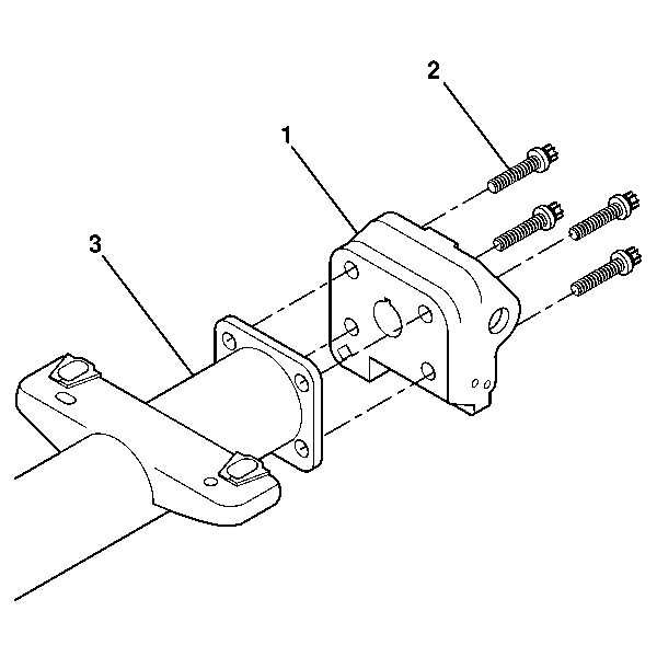
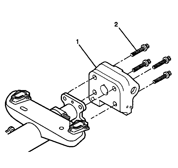
- Remove the 4 TORX® head screws (2).
- Remove the steering column support assembly (1) from the telebearing and jacket assembly.
Caution: This vehicle is equipped with a Supplemental Inflatable Restraint (SIR) System. Failure to follow the correct procedure could cause the following conditions:
• Air bag deployment • Personal injury • Unnecessary SIR system repairs • Refer to SIR Component Views in order to determine if you are performing service on or near the SIR components or the SIR wiring. • If you are performing service on or near the SIR components or the SIR wiring, disable the SIR system. Refer to Disabling the SIR System.
Important: Carefully mark the parts to ensure proper assembly. Failure to assemble properly will cause the steering wheel to be turned 180 degrees.
Steering Shaft, Lower Bearing, and Jacket - Disassemble - Off Vehicle Non-Telescoping
Tools Required
J 21854-01 Pivot Pin Remover
- Disable the inflatable restraint steering wheel module. Refer to Disabling the SIR System in SIR.
- Remove the signal switch housing. Refer to Turn Signal Switch Housing - Disassemble - Off Vehicle .
- Remove the tilt spring. Refer to Tilt Spring - Disassemble - Off Vehicle .
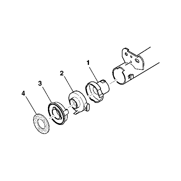
- Remove the steering shaft seal (4).
- Remove the sensor retainer (3).
- Remove the dual triangle sensor assembly (2).
- Remove the adapter and bearing assembly (1).
- Remove the 2 pivot pins (1) from the steering column support assembly using J 21854-01 .
- Install the tilt lever.
- Pull the tilt lever to disengage the steering column lock shoes from the dowel pins in the steering column tilt head assembly.
- Remove the steering column tilt head assembly (1) with the steering shaft assembly from the steering column jacket assembly.
- Remove the steering shaft assembly (2) from the steering column tilt head assembly (1).
- Mark the race and upper shaft assembly.
- Mark the lower steering shaft assembly.
- Tilt the race and upper shaft assembly 90 degrees to the lower steering shaft assembly to disengage.
- Remove the 4 TORX® head screws (2).
- Remove the steering column support assembly (1) from the steering column jacket assembly (3).
Caution: This vehicle is equipped with a Supplemental Inflatable Restraint (SIR) System. Failure to follow the correct procedure could cause the following conditions:
• Air bag deployment • Personal injury • Unnecessary SIR system repairs • Refer to SIR Component Views in order to determine if you are performing service on or near the SIR components or the SIR wiring. • If you are performing service on or near the SIR components or the SIR wiring, disable the SIR system. Refer to Disabling the SIR System.
Important: Carefully mark the parts to ensure proper assembly. Failure to assemble properly will cause the steering wheel to be turned 180 degrees.