Radiator Support Replacement for Chevrolet Malibu 2001
Removal Procedure
- Remove all related panels and components.
- Visually inspect and restore as much of the damage as possible to factory specifications.
- Remove sealers and anti-corrosion materials as necessary.
- Locate, mark and drill out all factory welds as necessary. Note the number of welds for installation of the service panels.
- Remove the damaged panels in the upper tie bar assembly and the front end lower brace, as necessary.
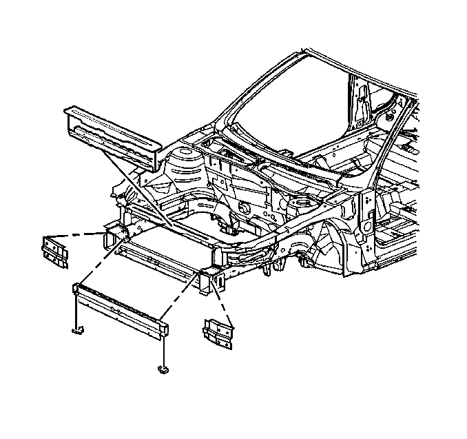
Important: The front end structure consists of six resistance-welded components. The upper tie bar and upper reinforcement panel are serviced as individual components. The brace, (front-end lower structure), includes rail reinforcement gussets, which provide cross-car alignment of the service assembly. The left and right impact bar brackets are serviced separately and must be installed using three-dimensional coordinates.
Installation Procedure
- Prepare mating surfaces and check for proper fit of the service panels.
- Drill 8 mm (5/16 in) plug weld holes in the locations noted from the original assembly on the service panels.
- Position the service panels.
- Check fit using body dimensions.
- Plug weld accordingly with frequent measurements to ensure proper fit.
- Clean and prepare welded surfaces.
- Apply approved anti-corrosion primer.
- Apply sealers and refinish as necessary.
- Install all related panels and components.
Important: If original components are damaged beyond recognition, place plug weld holes every 40 mm (1 ½ in) apart.
Important: Do not combine paint systems. Prior to refinishing, refer to GM P/N 4901MD-99 Refinish Manual for recommended products. Refer to paint manufacturer's recommendations.
Important: Upper tie-bar service parts do not have mounting location for the three center latch support holes. Use threaded inserts such as Riv-nuts, available through Kent-Moore™ tools Riv-nut Kit P/N 42151-8 MS.
