Diagnostic Instructions
| • | Perform the Diagnostic System Check - Vehicle prior to using this diagnostic procedure. |
| • | Review Strategy Based Diagnosis for an overview of the diagnostic approach. |
| • | Diagnostic Procedure Instructions provides an overview of each diagnostic category. |
DTC Descriptors
DTC B0012: Passenger Frontal Deployment Loop (Stage 2) Resistance LowDTC B0013: Passenger Frontal Deployment Loop (Stage 2) Open
DTC B0014: Passenger Frontal Deployment Loop (Stage 2) Voltage Out of Range
DTC B0016: Passenger Frontal Deployment Loop (Stage 1) Resistance Low
DTC B0017: Passenger Frontal Deployment Loop (Stage 1) Open
DTC B0018: Passenger Frontal Deployment Loop (Stage 1) Voltage Out of Range
Diagnostic Fault Information
Circuit | Short to Ground | High Resistance | Open | Short to Voltage | Signal Performance |
|---|---|---|---|---|---|
I/P Module Stage 1 High Circuit | B0018 | B0018 | B0017 | B0018 | B0016 |
I/P Module Stage 1 Low Circuit | B0018 | B0018 | B0017 | B0018 | B0016 |
I/P Module Stage 2 High Circuit | B0014 | B0014 | B0013 | B0014 | B0012 |
I/P Module Stage 2 Low Circuit | B0014 | B0014 | B0013 | B0014 | B0012 |
Circuit/System Description
The passenger deployment loop consists of a dual stage inflatable restraint instrument panel (I/P) module. The I/P module high circuits, and the I/P module low circuits exist for both stages 1 and 2. There are 2 shorting bars used within the I/P module connector. These shorting bars short together the I/P module stage 1 high circuits, and low circuits, and the I/P module stage 2 high circuits and low circuits when the connector is disconnected. This prevents unwanted deployment of the inflator module during servicing. During a frontal crash of sufficient force the inflatable restraint sensing and diagnostic module (SDM) will allow current to flow through the deployment loop. This flow of current will deploy the I/P module. The SDM performs continuous diagnostic tests on the deployment loops to check for proper circuit continuity, and for shorts-to-ground or voltage. If a malfunction is detected, a diagnostic trouble code (DTC) will be stored in memory.
Conditions for Running the DTC
Ignition voltage is between 9-16 volts.
Conditions for Setting the DTC
B0012 stage 2 or B0016 stage 1
The I/P module deployment loop resistance is less than 1.3 ohms for 500 milliseconds.
B0013 stage 2 or B0017 stage 1
| • | The I/P module stage 1 or stage 2 high circuit is less than 2.4 volts and the I/P module stage 1 or stage 2 deployment loop is more than 6 ohms for 500 milliseconds. |
| • | The I/P module stage 1 or stage 2 deployment loop resistance is more than 4.8 ohms for 500 milliseconds. |
B0014 stage 2 or B0018 stage 1
| • | The I/P module stage 1 or stage 2 high and/or low circuits is short to ground or short to voltage for 500 milliseconds. |
| • | The I/P module stage 1 or stage 2 high circuit is less than 2.4 volts and I/P module stage 1 or stage 2 deployment loop resistance is less than 6 ohms for 500 milliseconds. |
Action Taken When the DTC Sets
| • | The SDM requests the instrument panel cluster (IPC) to illuminate the AIR BAG indicator. |
| • | The SIR system is disabled and no deployments are allowed. |
Conditions for Clearing the DTC
| • | The condition responsible for setting the DTC no longer exists. |
| • | A history DTC will clear once 100 malfunction-free ignition cycles have occurred. |
Diagnostic Aids
If there is more than one DTC set diagnose the open DTC first. The following are possible causes of the malfunction:
| • | A short between the I/P module stage 1 or stage 2, high and low circuits |
| • | An open or a high resistance in the I/P module stage 1 or stage 2, high or low circuits |
| • | A short to ground or a short to voltage in the I/P module stage 1 or stage 2, high or low circuits |
| • | A malfunctioning I/P module connector |
| • | A malfunctioning SDM connector |
| • | A malfunctioning I/P module |
| • | A malfunctioning SDM |
Reference Information
Schematic Reference
Connector End View Reference
Description and Operation
SIR System Description and Operation
Electrical Information Reference
Special Tools
| • | J 38715-A Driver/Passenger Load tool |
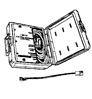
| • | EL 38715-125 Load Tool Adapter |
Circuit/System Testing
Important: When removing connectors inspect for damage or corrosion. Damage or corrosion to the following requires repair or replacement of the affected component/connector:
• I/P module • SDM module • I/P wiring harness connector • SDM wiring harness connector
- Verify that the I/P module connector and the CPA are engaged.
- Ignition OFF, disconnect I/P module in-line connector.
- Use J 38715-125 to connect the J 38715-A to the harness side of the I/P module in-line wiring harness connector. Use the PASSENGER INFLATOR and BASE of COLUMN connectors located on the load tool.
- Ignition ON, use a scan tool to observe the SIR DTC display. Verify DTC B0012, B0013, B0014, B0016, B0017, or B0018 is current.
- Ignition OFF, disconnect and remove the J 38715-A and adapter.
- Disconnect the SDM harness connector.
- Ignition ON, test for less than 1 volt between the appropriate high control circuit listed below and ground:
- Test for less than 1 volt between the appropriate low control circuit terminal listed below and ground:
- Ignition OFF, test for infinite resistance between the appropriate high control circuit terminal listed below and ground:
- Test for infinite resistance between the appropriate low control circuit terminal listed below and ground:
- Test for less then 1 ohm between the appropriate high control circuit terminals listed below.
- Test for less then 1 ohm between the appropriate low control circuit terminals listed below:
- If all circuits test normal, replace the SDM.
Important: The connector and connector position assurance (CPA) may seat independent of each other. Both the connector and CPA should seat with an audible and/or tactile click. The CPA isolates the shorting-bars within the connector allowing the deployment circuit to operate properly.
| ⇒ | If DTC B0012, B0013, B0014, B0016, B0017, or B0018 is not set or set as history, cycle ignition OFF, disconnect the adapter and J 38715-A , reconnect the harness connector at the I/P module, and cycle the ignition ON. If the DTC resets after reconnecting the module, replace the I/P module. |
| • | I/P module Stage 1 terminal A X1 |
| • | I/P module Stage 2 terminal A X2 |
| ⇒ | If greater than the specified range, test the control circuit for a short to voltage. |
| • | I/P module Stage 1 terminal B X1 |
| • | I/P module Stage 2 terminal B X2 |
| ⇒ | If greater than the specified range, test the control circuit for a short to voltage. |
| • | I/P module Stage 1 terminal A X1 |
| • | I/P module Stage 2 terminal A X2 |
| ⇒ | If less than the specified value, test the control circuit for a short to ground. |
| • | I/P module Stage 1 terminal B X1 |
| • | I/P module Stage 2 terminal B X2 |
| ⇒ | If less than the specified value, test the control circuit for a short to ground. |
| • | I/P module Stage 1 terminal A X1 and SDM terminal A4 |
| • | I/P module Stage 2 terminal A X2 and SDM terminal B4 |
| ⇒ | If greater than the specified range, test the control circuit for an open/high resistance. |
| • | I/P module Stage 1 terminal B X1 and SDM terminal A3 |
| • | I/P module Stage 2 terminal B X2 and SDM terminal B3 |
| ⇒ | If greater than the specified range, test the control circuit for an open/high resistance. |
Repair Instructions
Perform the Diagnostic Repair Verification after completing the diagnostic procedure.
| • | Control Module References for SDM replacement, setup, and programming |
