For 1990-2009 cars only
Heater and Air Conditioning Control Replacement for Holden Captiva 2007
Heater and Air Conditioning Control Replacement C100/Long Body
Removal Procedure
- Disconnect the negative battery cable. Refer to Battery Negative Cable Disconnection and Connection .
- Remove the instrument panel accessory bezel. Refer to Instrument Panel Accessory Bezel Replacement .
- Remove the four controller retaining screws.
- Pull out the unit to gain access to rear.
- Disconnect the electrical connectors.
- Remove the control assembly.
Caution: Refer to Battery Disconnect Caution in the Preface section.
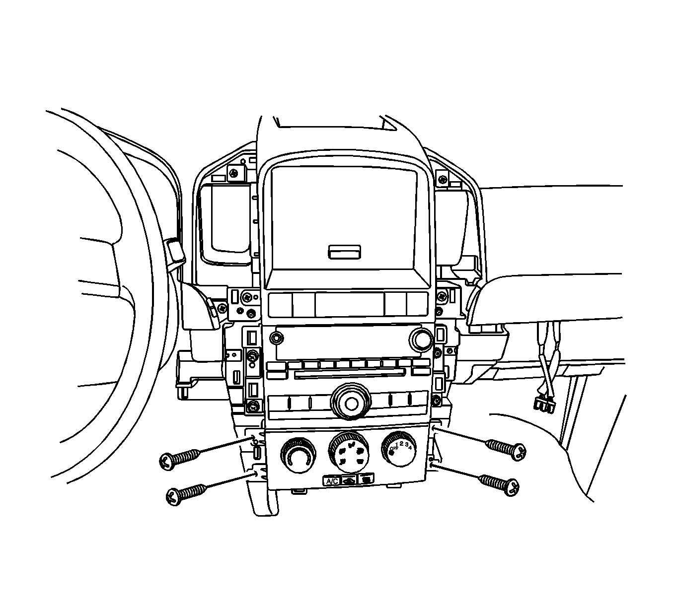
Important: The left-hand drive is shown. The right-hand drive is similar.
Installation Procedure
- Connect the electrical connectors to the sockets on the back of the controller.
- Gently insert the controller into position on the center console.
- Install the retaining screws.
- Connect the negative battery cable. Refer to Battery Negative Cable Disconnection and Connection .
- Confirm the proper operation of the controller by moving it through all of the controller's possible functioning positions.
- Install the instrument panel accessory bezel. Refer to Instrument Panel Accessory Bezel Replacement .
Notice: Refer to Fastener Notice in the Preface section.
Tighten
Tighten the controller retaining screws to 2.5 N·m (22 lb in).
Heater and Air Conditioning Control Replacement C105/Short Body
Removal Procedure
- Disconnect the negative battery cable.
- Remove the instrument panel accessory bezel. Refer to Instrument Panel Accessory Bezel Replacement .
- Remove the four control assembly retaining screws.
- Disconnect the electrical connectors.
- Remove the manual temperature control assembly.
Caution: Refer to Battery Disconnect Caution in the Preface section.
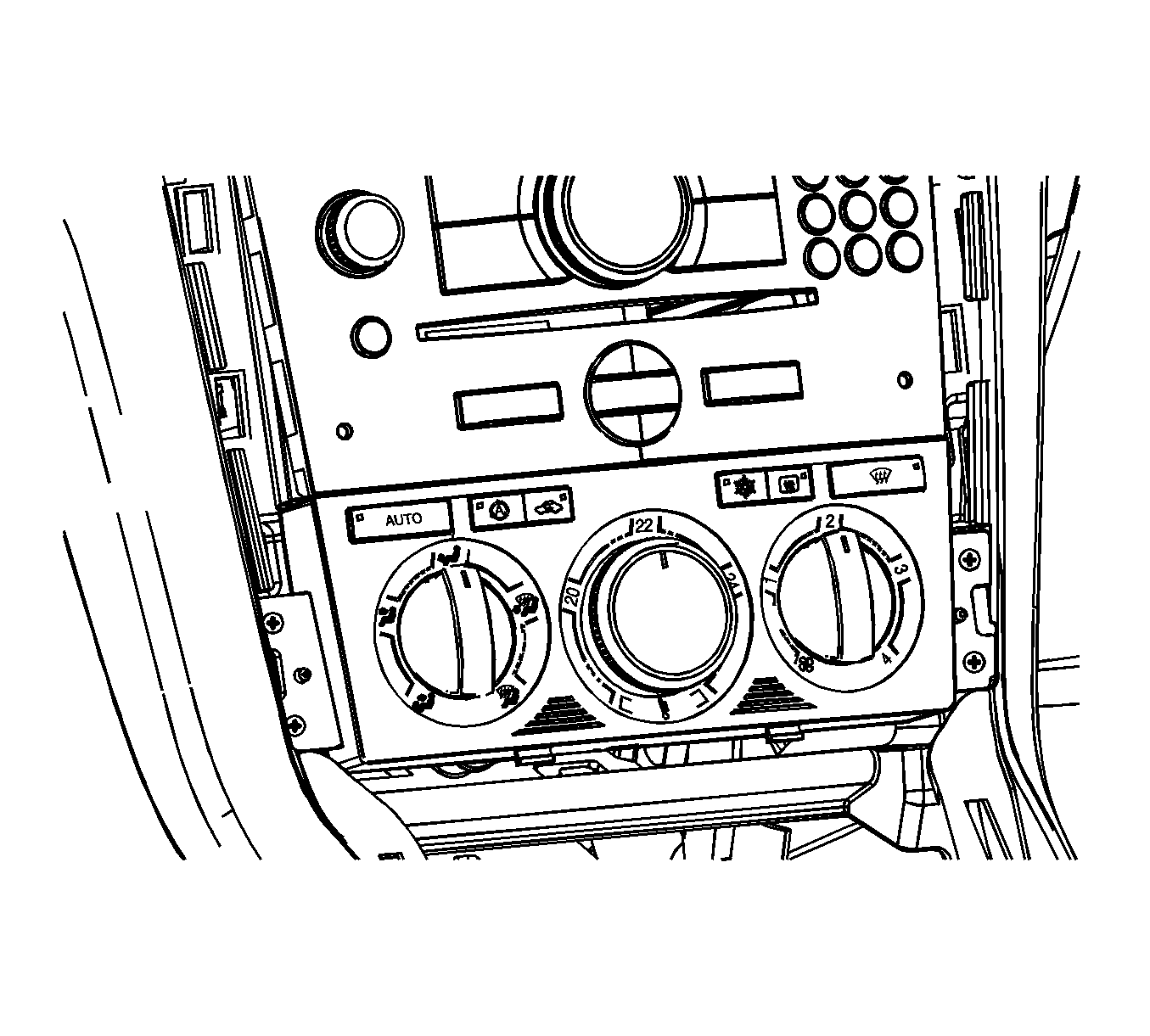
Important: The left-hand drive is shown. The right-hand drive is similar.
Installation Procedure
- Connect the electrical connectors to the sockets on the back of the controller.
- Carefully insert the controller into position on the center console.
- Install the retaining screws.
- Connect the negative battery cable. Refer to Battery Negative Cable Disconnection and Connection .
- Confirm the proper operation of the controller by moving it through all of the controller's possible functioning positions.
- Install the instrument panel accessory bezel. Refer to Instrument Panel Accessory Bezel Replacement .
Notice: Refer to Fastener Notice in the Preface section.
Tighten
Tighten the control assembly retaining screws to 2.5 N·m (22 lb in).
