Step | Action | Value(s) | Yes | No |
|---|---|---|---|---|
1 | Was the entire Data Link Connector (DLC) system check performed? | -- | Go to Step 2 | |
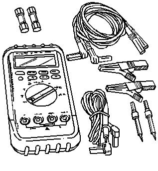
2 | Use a J 39200 digital multimeter (DMM) in order to measure the voltage between B+ and DLC terminal 5. Is the voltage within the specified range? | B+ (9-14 V) | Go to Step 3 | Go to Step 4 |
3 | Inspect for proper connection of the scan tool to the DLC. Is the connection OK between the scan tool and the DLC? | -- | Go to Step 5 | Go to Step 6 |
4 | Repair the poor connection or an open in circuit 1550 between the DLC and S211. Is the repair complete? | -- | Go to Step 18 | -- |
5 | Attempt to establish communication with the radio on a different vehicle using the scan tool. Can communication be established with the scan tool? | -- | Go to Step 7 | Go to Step 8 |
6 | Repair the poor connection between the DLC terminal 14 and the scan tool. Is the repair complete? | -- | Go to Step 18 | -- |
7 |
Can the scan tool communicate with the radio? | -- | Go to Step 9 | Go to Step 10 |
8 | The scan tool may be malfunctioning. Refer to the scan tool instruction manual for additional information. Is the action complete? | -- | Go to Step 18 | -- |
9 |
Is the repair complete? | -- | Go to Step 18 | -- |
10 |
Is the resistance the same as the specified value? | ∞ | Go to Step 11 | Go to Step 12 |
11 |
Is the voltage within the specified value? | Less than 1 V | Go to Step 13 | Go to Step 14 |
12 | Repair the short to ground in circuit 835. Is the repair complete? | -- | Go to Step 18 | -- |
13 | Use a J 39200 DMM in order to measure the resistance between the DLC terminal 14 and the radio harness connector C2 terminal 15. Is the resistance within the specified value? | 0-2ohms | Go to Step 15 | Go to Step 16 |
14 |
Is the repair complete? | -- | Go to Step 18 | -- |
15 |
Can the scan tool communicate with the radio? | -- | Go to Step 18 | Go to Step 17 |
16 | Repair the poor connection or an open in circuit 835. Is the repair complete? | -- | Go to Step 18 | -- |
17 | Inspect for power, ground and proper connections to the radio. Refer to Radio/Audio System Check in Entertainment for additional information. Is the action complete? | -- | Go to Step 18 | -- |
18 |
Is the action complete? | -- | -- |