Diagnostic Instructions
Circuit/System Description
The keyless entry system is a vehicle entry device. The keyless entry will unlock/unlatch the vehicle doors or open the rear gate when a corresponding button on the key fob is pressed. This is accomplished by the key fob sending a radio frequency to the
body control module (BCM). The signal is received by the BCM via an internal antenna. A low transmitter battery or radio frequency (RF) interference from aftermarket devices such as 2-way radios, power inverters, cellular phone chargers, computers, etc. may
cause a system malfunction. High RF traffic areas, such as gas stations which use pay-at-the-pump RF transponders, may also cause interference that could lead to a malfunction.
Diagnostic Aids
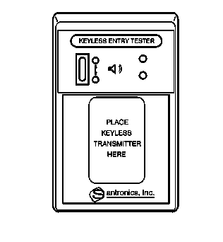
For the
J 43241
Keyless Entry Tester, inspect the keyless entry transmitter part number to determine that it is the correct model for the vehicle. A wrong model transmitter may pass the test, but it
will not activate the vehicle remote system.
Reference Information
Schematic Reference
Remote Function Schematics
Electrical Information Reference
Scan Tool Reference
Scan Tool Data List
Circuit/System Testing
- Ignition On, verify the scan tool Remote Panic Command parameter responds to the panic function on the transmitter.
- Verify that the headlamps pulse ON and OFF when the panic button is pressed.
- Refer to
Diagnostic Starting Point - Horns
.
Repair Instructions
Perform the
Diagnostic Repair Verification
after completing the diagnostic procedure.